Clause 2.5 SS Door
2.5.1 Opening Dimensions
The opening dimensions of SS door shall be:
a. For SS – 900(W) mm x 1900(H) mm
b. For S/C SS and scissor S/C SS
i. For entrance SS door, the dimension shall be 900(W) mm or 1000(W) mm x 2055(H) mm.
ii. For internal SS door at mid-landing or main landing in the staircase, the dimension shall be 1000(W) mm x 2055(H) mm.
c. SS door frame that is cast together with the SS wall shall have single or double door rebate. Refer to FIGURE 2.5.1(a) and 2.5.1(b).
F2.5.2 Location
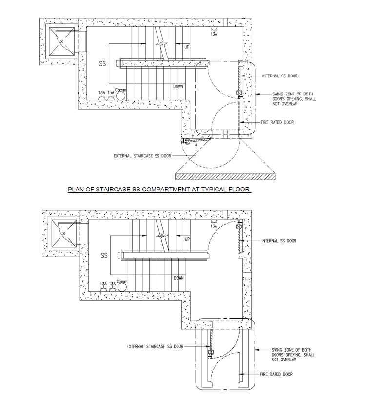
The SS door shall be located in a SS wall with a minimum setback distance of 3000mm and shall not swing in a direction that will clash with the swing path of another peacetime door. Refer to FIGURE 2.5.2.
F2.5.3 Door Frame
a. There shall be a minimum 150mm reinforced concrete wall segment next to vertical edge of SS or S/C SS door frame. Refer to FIGURE 2.5.3(a) and 2.5.3(c).
Fb. For pre-cast door frame panel of Type 1, the reinforced concrete next to two vertical edges of the SS door frame shall be 300mm each. Refer to FIGURE 3.5.5(a).
Fc. For pre-cast door frame panel of Type 2, the reinforced concrete next to vertical edges of the SS door frame shall be 300mm on one side, and 150mm plus the SS wall thickness on the other side. Refer to FIGURE 3.5.5(f).
Fd. For pre-cast door frame panel of Type 3, the reinforced concrete panel with full length or width of SS wall must be properly connected to the in-situ SS walls and slabs. Refer to FIGURE 3.5.5(k).
Fe. The SS or S/C SS door frame must be positioned such that its door is above FFL and can be opened at least 90°. Refer to FIGURE 2.5.3(b) and 2.5.3(d).
F2.5.4 Shielding Wall
a. A full-height reinforced concrete shielding wall, with a minimum thickness of 200mm (with protective slab extended by at least ½ of storey height from the shielding wall) or 300mm (if the protective slab is extended by less than ½ of storey height), has to be provided in front of the entrance SS door.
b. The shielding wall to the SS door can be positioned and arranged in the following manner:
i. A shielding wall has to be positioned such that it is at least 1200mm but not more than 3000mm from the SS door and is within influence zone of 45-degree from the SS door. Refer to FIGURE 2.5.4(a) to 2.5.4(f). The shielding wall forming part of the dwelling unit’s wall shall be clearly indicated on plans.
Fii. The shielding wall shall be protected by floor slab or trellis of at least half the storey height measured from the shielding wall. Refer to FIGURE 2.5.4(a), 2.5.4(b), 2.5.4(d) to 2.5.4(f).
Fiii. Where the lift shaft is facing the SS door, the RC wall of the shaft can be used as a shielding wall provided its thickness is at least 200mm. Refer to FIGURE 2.5.4(c). For such case, the surrounding lift shaft wall and roof slab of lift motor room shall be reinforced concrete.
Fiv. For service risers located within influence zone, the RC walls of the risers can be used as shielding wall provided its thickness is at least 200mm. Refer to FIGURE 2.5.4(e).
Fv. Where the shielding wall located within influence zone is discontinuous, the opening in this wall shall not be in the line of sight of SS door. In the case of the opening not in the line of sight of SS door but facing the SS wall, there shall be RC slabs with a minimum distance of 8000mm provided from the SS wall. Refer to FIGURE 2.5.4(d) and 2.5.4(f).
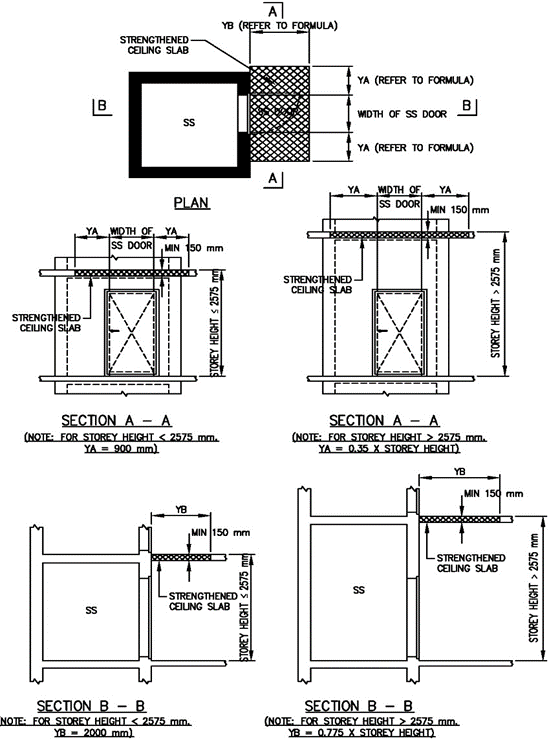
F2.5.5 Strengthened Ceiling Slab outside SS Door
 ) or https:// as an added precaution. Share sensitive
information only on official, secure websites.

.png?sfvrsn=28721c7f_2)
.png?sfvrsn=7a2f9460_2)

.png?sfvrsn=9e00370d_2)
.png?sfvrsn=af1b6f2b_2)
.png?sfvrsn=5a8d8fcb_2)
.png?sfvrsn=d3552fc2_2)
.png?sfvrsn=d557e286_2)
dcb74daad7f8408497e1254c65db3730.png?sfvrsn=2e4f0d1e_2)
.png?sfvrsn=db52b1ee_2)
.png?sfvrsn=cd8ac85e_2)
.png?sfvrsn=e6b31e67_2)
.png?sfvrsn=b12aeb1d_2)
.png?sfvrsn=896a2b7f_2)
.png?sfvrsn=a08c24ca_2)
.png?sfvrsn=590d05c9_2)
