Clause 3.3 Analysis
3.3.1 General
The vertical continuity of SS and NS walls, where applicable, to the foundation shall comply with Clause 2.4.2. In the case of S/C SS or scissor S/C SS tower, the SS and NS wall shall be continuous to foundation, except where there are fire discharge openings at fire discharge levels. The fire discharge openings shall be located such that all corners of the S/C SS walls are continuous to foundation.
3.3.2 Beam Supported on SS wall
The end of the external beam that is supported on SS wall(s) shall be designed and detailed as simply support.
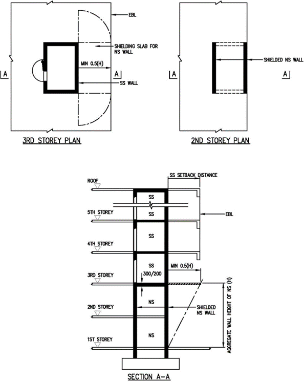
3.3.3 Shielded NS Walls (2 opposite NS wall [not applicable for S/C SS tower] or 4 NS walls)
No additional design checks on SS tower is required if its supporting wall(s) are shielded. These structural walls are deemed shielded if reinforced concrete slab or other equivalent structural forms provided above them is extended beyond their edges by as minimum length of 0.5H, where H is the aggregate wall height of NS (See FIGURE 3.3.3 and 3.3.4(c)).
F3.3.4 Unshielded NS Walls (2 opposite NS walls [not applicable for S/C SS tower] or 4 NS walls)
The following requirements are to be complied with if the design adopts:
a. Unshielded NS Walls
The minimum thickness of each NS wall shall be 300mm. The SS, S/C SS or scissor S/C SS tower shall be designed against the most severe effects as the result of the removal of a portion of the NS wall equivalent to an opening of 1500mm diameter on the NS wall at its most critical location (Refer to FIGURE 3.3.4(a), 3.3.4(b) and 3.3.4(d)).
Fb. The following are the criteria to be used when performing design checks for Clause 3.3.4(a):
i. The design shall be based on the action combination and values of partial safety factor for actions in accordance with Table 3.3.4.
Fii. The design strength for a given material is derived from the characteristic strength divided by the partial safety factor for strength of material, which shall be 1.2 for concrete and 1.0 for reinforcements.
 ) or https:// as an added precaution. Share sensitive
information only on official, secure websites.


.png?sfvrsn=8d7963da_2)
.png?sfvrsn=93c9017b_2)
.png?sfvrsn=cd2d8b0e_2)
.png?sfvrsn=391ef189_2)