Please enter a keyword to search
Use of plastic material shall be in accordance with the Code of Practice for Fire Precautions in Buildings, except where herein modified in this Code.
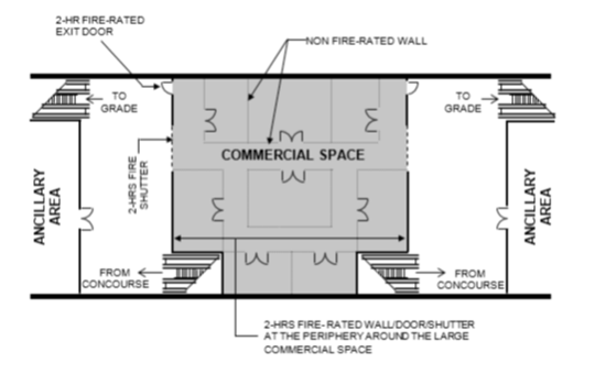
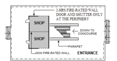
Diagram 3.2.4c.: Compartmentation of Commercial Spaces
Compartmentation of additional commercial spaces made up of a group of shops

Compartmentation of commercial spaces at the ground level of station entrance

Diagram 3.2.4c.: Compartmentation of Commercial Spaces
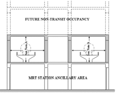
Diagram 3.3.2c.: Cross-Section of Trainway

Fire resistance of elements of structure around the trainway in an aboveground station where there are habitable floors directly above the trainway.
Note: All elements of structure shall not be less than 4 hrs fire rating.
Diagram 3.3.2c.: Cross-Section of Trainway
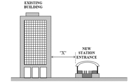
Diagram 3.5.2d.: Distance between Existing Building and New Station Entrance

Separation distance “X” between the external wall of a ground level entrance (with no habitable room) and the external wall of an adjacent building.
Diagram 3.5.2d.: Distance between Existing Building and New Station Entrance
TABLE 3.2A: SIZE LIMITATION OF STATION AND COMPARTMENT
| TABLE 3.2A: SIZE LIMITATION OF STATION AND COMPARTMENT | ||
| Compartments | Maximum Floor Area | Maximum Cubical Extent |
| (2) | (3) | |
| Compartment below ground level. No compartment to comprise more than one storey*. | 2000m2 | 7500m3 |
| Compartments between average ground level and a height of 24m. No compartment to comprise more than 3 storeys. | 4000m2 | 15000m3 |
| Compartments above a height of 24m from average ground level. No compartment to comprise more than one storey. | 2000m2 | 7500m3 |
Note: * = Size limitation of compartment below ground level is not applicable to the public area. Public area below ground level shall comply with Cl.3.2.4e. | ||
TABLE 3.4A: SPECIFIC PROVISIONS OF TEST FOR FIRE RESISTANCE OF ELEMENTS OF STRUCTURE ETC
| TABLE 3.4A: SPECIFIC PROVISIONS OF TEST FOR FIRE RESISTANCE OF ELEMENTS OF STRUCTURE ETC | ||||
| Part of station | Minimum provisions when tested to BS 476: Part 20-23 (mins) | Method of exposure | ||
| Stability | Integrity | Insulation | ||
| 1. Structural frame, beam, or column | * | no requirement | no requirement | exposed faces |
| 2. Loadbearing wall, which is not also an external wall, separating wall, compartment wall or protecting structure (See 4, 5, 6 or 7) | * | no requirement | no requirement | each side separately |
| 3. Floors | * | * | * | from underside |
| 4. External walls (a) any part less than 1m from point of relevant boundary | * | * | * | each side separately from inside |
| (b) any part 1m or more from the relevant boundary | * | * | * | |
| 5. Separating wall | * | * | * | each side separately |
| 6. Compartment wall | * | * | * | each side separately |
| 7. Protecting structure any part | * | * | * | each side separately |
| 8. Doors (a) in a separating wall | no provision | + | no provision | each side separately when fitted in its frame |
| (b) in a compartment wall | no provision | + | no provision | |
| (c) in a protecting structure | no provision | ** | no provision | |
| (d) any other door (including a door in a cavity barrier) | no provision | 30 | no provision | |
| 9. Cavity barrier (a) cavity barrier 1m x 1m or larger | 30 | 30 | 15 | each side separately |
| (b) any other cavity barrier | 30 | 30 | no provision | |
| (c) ceiling | 30 | 30 | 30 | from underside |
Note: * - Period of fire resistance as specified. ** - Half the period of fire resistance for the wall or floor in which the door is situated. + - Period of fire resistance for the wall or floor in which the door is situated. | ||||
TABLE 3.9A: MAXIMUM NOMINAL DIAMETER OF PIPES
| TABLE 3.9A: MAXIMUM NOMINAL DIAMETER OF PIPES | |||
| Situation | Pipe material and maximum nominal diameter [mm] | ||
| Non-combustible Material(1) | Lead, aluminium, or aluminium alloy or UPVC(2) | Any other material | |
| When the pipes (include pipe supports) penetrate the structure enclosing a protected shaft which is not an exit stairway or lift shaft | 150 | 100(5) | 40(5) |
| Any other situation | 150 | 100 (stack pipe)(3),(4),(5) | 40(5) |
| 75 (stack pipe)(3),(4),(5) | |||
Note: (1) A non-combustible material (such as for cast iron or steel pipes and the pipe supports with melting point of at least 1200ºC) which if exposed to a temperature of 750ºC will not soften nor fracture to the extent that flame or gases will pass through the wall of the pipe. (2) Unplasticised Poly Vinyl Chloride (UPVC) pipes shall comply with BS 4514 or EN 1329-1. Use of PVC pipes shall comply with Cl.3.15.1. (3) Within toilets, wash rooms or external corridors, maximum diameter of UPVC pipes can be increased to double the size given in the above table. (4) Within areas of fire risk and adjacent to escape routes, UPVC pipes shall be enclosed by construction having fire resistance of at least ½-hr. (5) Where the size of UPVC pipes exceeds that specified under this clause, approved fire collar shall be fitted at all positions where such pipes pass through constructions required to act as a barrier to fire spread. | |||

