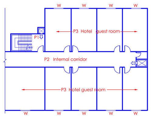
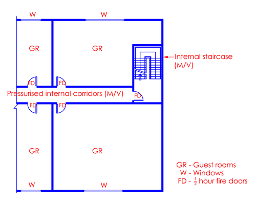
Figure 7.3.1 - 1
Provision of pressurisation to the internal corridor would help to check the migration of smoke from any of the guest rooms. The pressure gradient shall be such that :P1>P2>P3
Acceptable
More than 4 storeys
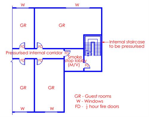
Figure 7.3.1 - 2 : Internal staircase with MV smoke-stop lobby
The above figure illustrates a mechanical ventilated smoke stop lobby and an internal staircase to be pressurised accordingly. The pressure gradient shall be such that the pressure at the exit staircase shall always be higher.

Acceptable
More than 4 storeys
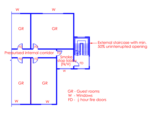
Figure 7.3.1 - 3 : External staircase with MV smoke-stop lobby
The smoke-stop lobby shall be provided with mechanical ventilation and the staircase shall be treated as an external staircase. The external staircase shall be provided with uninterrupted permanent openings having minimum 50% of the staircase plan area
(louvre is not allowed).
Acceptable
More than 4 storeys
Figure 7.3.1 - 4 : External staircase with NV smoke-stop lobby
The above figure illustrates a naturally ventilated smoke-stop lobby and external staircase. The smoke-stop lobby shall be provided with minimum 15% external openings. The external staircase shall be provided with uninterrupted permanent openings having
minimum 50% of the staircase plan area (louvre is not allowed).
Not more than 4 storeys
Acceptable
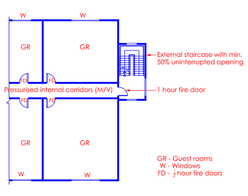
Figure 7.3.1 - 5 : External staircase without smoke-stop lobby
The internal corridor leading to the exit should be via a minimum 1-hr fire resistance door. The external staircase shall be provided with uninterrupted permanent openings having 50% of the staircase plan area (louvre is not allowed).
Not more than 4 storeys
Acceptable
Figure 7.3.1 - 6 : Internal staircase without smoke-stop lobby
In the above figure, the provision of smoke-stop lobby is not required by virtue of its height under Cl.2.2.13.
The staircase is an internal staircase, as such it shall be pressurised to have a higher pressure differential than the internal corridor.
Not more than 4 storeys
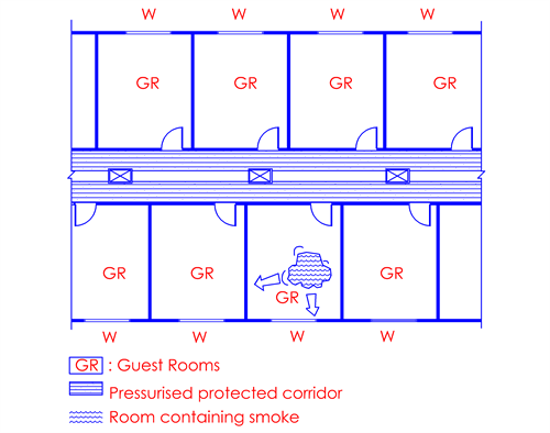
Figure 7.3.1 - 7 : Pressurisation system for hotel
The above figure shows a simple pressurisation system suitable for small hotels. It consists of fans, which are connected to smoke sensitive device so that they operate in fire emergency. The corridor shall be provided with pressurisation to maintain
a positive pressure. The power and capacity of the fan is calculated after evaluation of air leakage factors, so that an adequate pressure differential can be developed between the corridor and the guest rooms.
For effective pressurisation, there must be sufficient leakage through the external envelope of the building so that the pressure in the fire room will not reach the same pressure level with the pressure in the protected corridor.

