2.5 SPECIAL REQUIREMENTS FOR PERSON WITH DISABILITIES (PWDs)
2.5.1 General
Effective Date: 1 Sep 2024
a. The scope of these requirements on the design and management of transit stations covers the public area of transit stations and excludes RTS depots, ancillary buildings, viaducts, and tunnels. These requirements are intended for the safe evacuation of PWDs during fire emergency.
b. Transit station public areas are designed with barrier-free accessibility under the Building Control Act. The ingress/ egress routes for PWDs shall also be used as evacuation routes for PWDs.
c. Transit stations are of non-combustible construction. The station public areas are segregated from the ancillary areas by fire-rated construction and are designed with emergency ventilation system to provide a tenable environment for evacuation in the event of fire emergency.
d. Passenger lifts in stations are primarily provided for use by PWDs. These lifts that are located in the public area shall be used for the evacuation of PWDs.
e. Management procedures and responsibilities shall be formulated for the evacuation of PWDs in the event of fire.
f. The evacuation route for PWDs in the public areas shall comply with the requirements of the authority having jurisdiction on accessibility in the Built Environment.
g. The requirements in Section 2.5 do not apply to stations/ areas exempted from barrier-free accessibility compliance, as required by the authority having jurisdiction on accessibility in the built environment.

Diagram: 2.2.4d. island Platform

For the fire doors, see hardware and other requirements for doors in Cl.3.9.2.
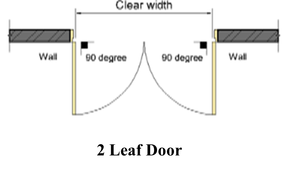
Sequential door closer shall be provided to both leaves.
Automatic flush bolt shall be provided. See Cl.2.2.17i..
For fire doors, automatic self-closing devices on both door leaves and sequence selector shall be provided.
Diagram 2.2.17c.(1): Measurement of Door Width
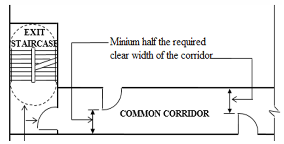
Door shall not encroach into the required width of the landing during its swing
Minimum width of corridor as required under Cl.2.2.3h., Cl.2.2.4f., and Cl.2.2.8.
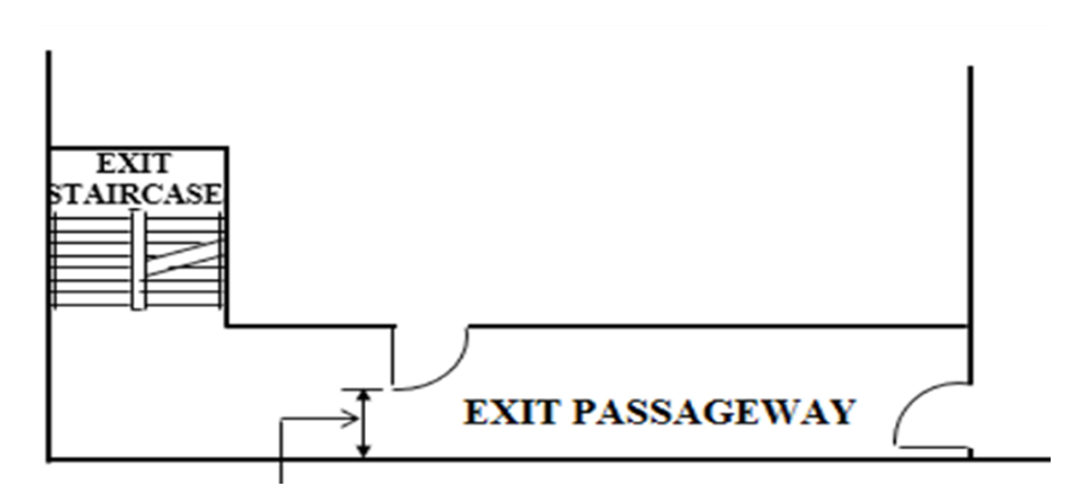
Exit doors shall not impede the egress of occupants when such doors are swung open.
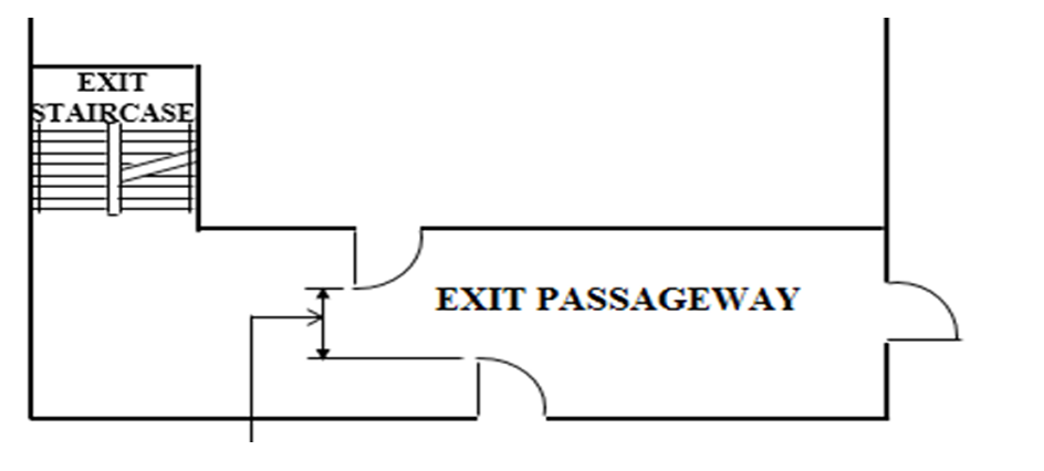
Minimum ½ width of corridor as required under Cl.2.2.3h., Cl.2.2.4f., and Cl.2.2.8.
Diagram 2.2.17e.(1): Exit Doors Opening into Exit Staircases and Exit Passageways
Remoteness of Exits
Diagram 2.2.19a. - 1 |
Diagram 2.2.19a. - 2 |
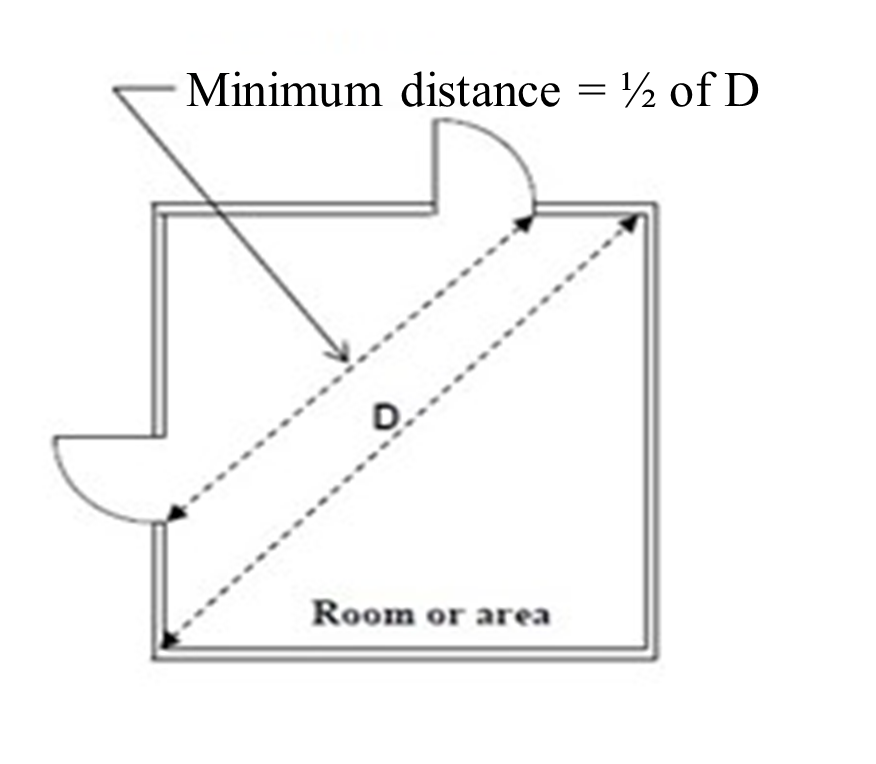
The distance between the two staircases is less than half the length of the maximum overall diagonal dimension of the area Diagram 2.2.19a. - 3 | 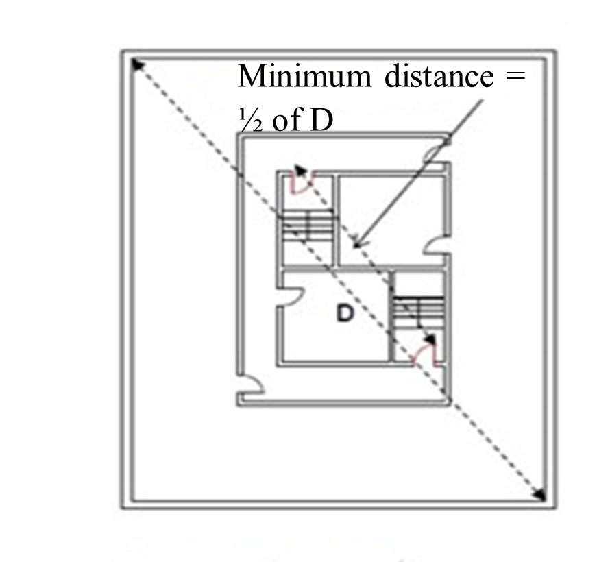 Two-way escape arrangement The distance between the two staircases is less than half the length of the maximum overall diagonal dimension of the area Diagram 2.2.19a. - 4 |
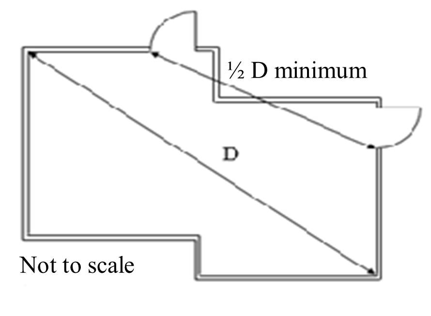 Diagram 2.2.19a. - 5 |  Diagram 2.2.19a. - 6 |

Remoteness of exits is measured along the 1-hr rated corridor with ½ hr fire doors
Diagram 2.2.19c.: Remoteness of Exit
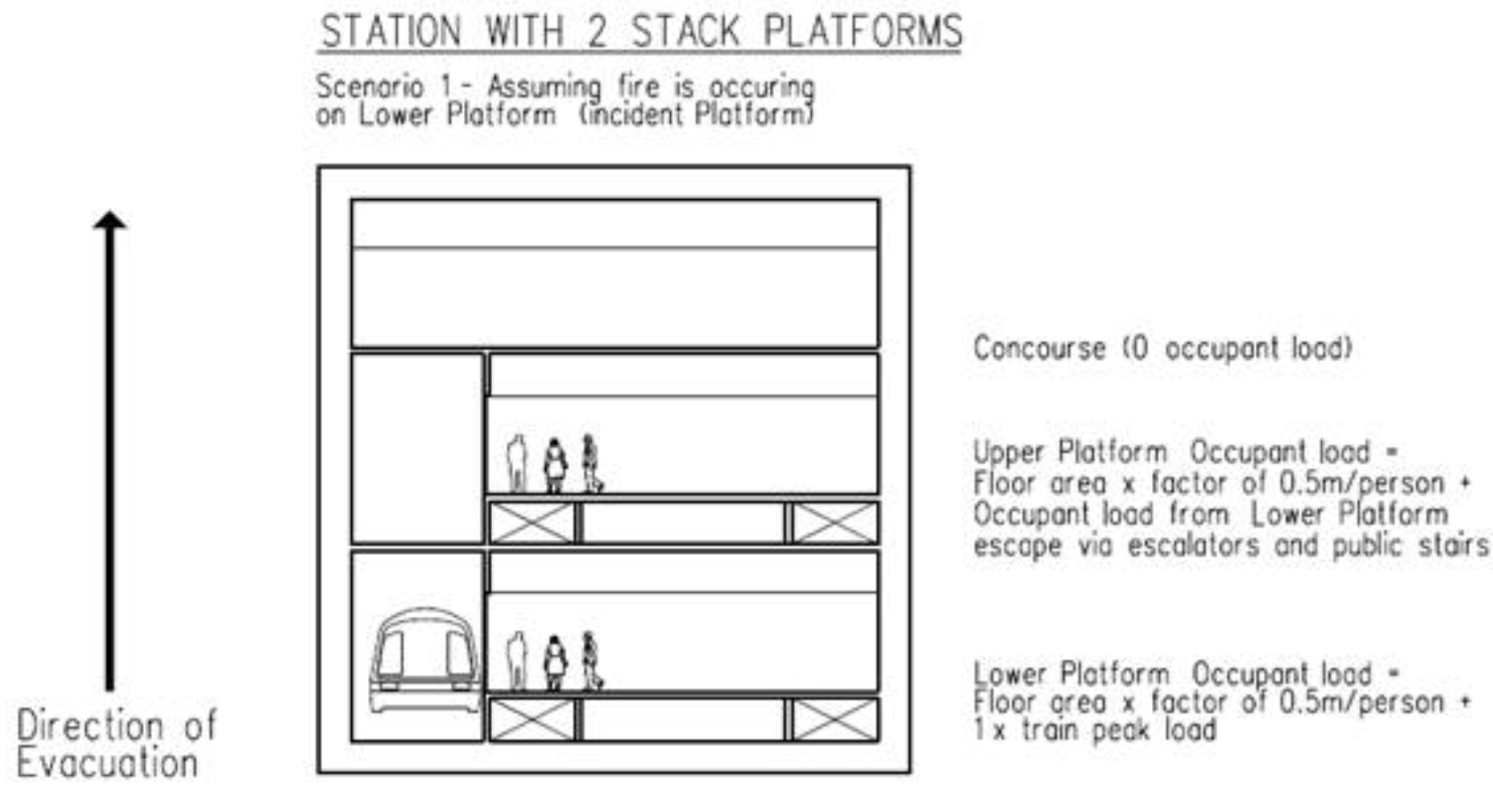
Diagram 2.3.2 – 1
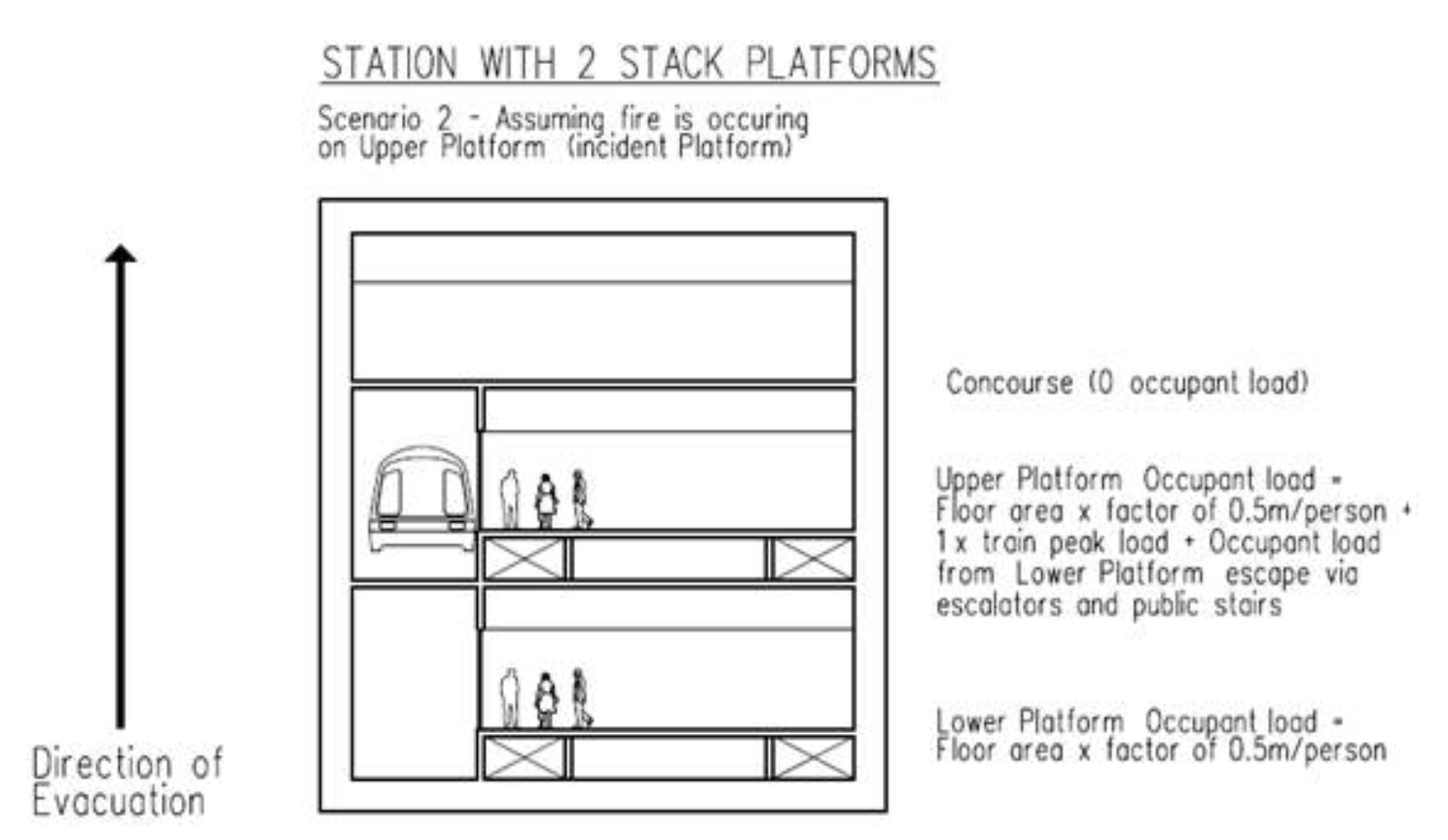
Diagram 2.3.2 – 2

Diagram 2.4.2 – 1
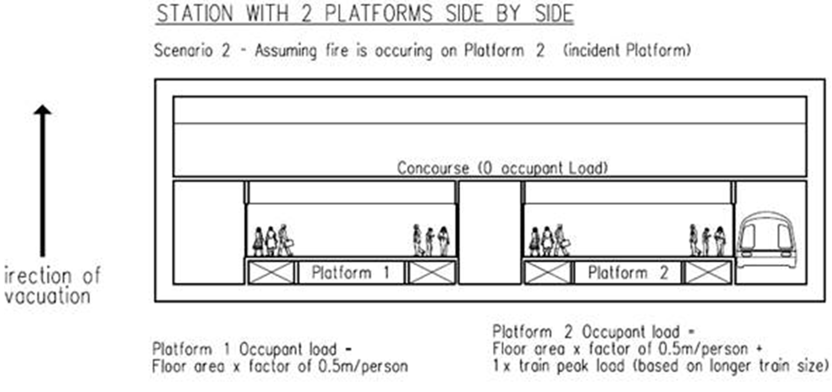
Diagram 2.4.2 – 2
| TABLE 2.2.2d.: OCCUPANCY LOAD FOR COMMERCIAL SPACES | |
|---|---|
| FUNTIONAL SPACES | OCCUPANCY LOAD (m2/person) |
| Reception Area | 3 |
| Lobby/ Corridors | * |
| Fixed Corridors | * |
| Waiting Area/ Visitors Lounge | 3 |
| Atrium Floor | 3 |
| Exhibition/ Promotion Area | 1.5 |
| Shop Floor | 5 |
| Showroom | 5 |
| Supermarket/ Bazaar | 5 |
| Department Store | 5 |
| Admin. Office | 10 |
| Toilets/ Staff Rest Room | * |
| Storage | 30 |
| Mechanical Plant Room | 30 |
| Classroom | 1.5 |
Note: * - not considered for occupant load calculation | |
| TABLE 2.2.3h.: CAPACITY OF MEANS OF ESCAPE | ||
|---|---|---|
| Type of Means of Escape | Capacity (p/m/min) | Travel Speed (m/min) |
| Platforms, corridors, and ramps not more than 4% in slope | 80(1) | 60 |
| Stairs, escalators, and ramps greater than 4% in slope | 60(2) | up 15(3) |
| down 18(3) | ||
| Doors and gates(5) | 80(4) | N/A |
|
Note: (1) - In calculating the capacity of horizontal means of escape routes with a slope not exceeding 4%, 300mm shall be deducted at each sidewall and 450mm at platform edges. (2) - Refer to Cl.2.2.3c.(2) with respect to the allowable means of escape contribution for escalators. |
||
| TABLE 2.2.4f.: CAPACITY OF EXIT FACILITIES | |
|---|---|
| Type of Means of Escape | Capacity (1) No. of person per unit of width (2) |
| Exit & corridor doors(3) | 80 |
| Staircases | 60 |
| Ramps, corridors & exit passageways | 100 |
|
Note: (1) - Where a room or space is required to be provided with two exits, each exit shall be of sufficient width to accommodate at least one half the total occupant load.
|
|
| TABLE 2.2.4g.: TRAVEL DISTANCE | |||
|---|---|---|---|
| Occupancy | Means of escape | Maximum travel distance (m) |
|
| Sprinkler-protected/ Open-to-sky | Non-sprinkler- protected | ||
| Commercial | One-way | 25 | 15 |
| Two-way | 60 | 45 | |
| Ancillary* | One-way | 30 | 15 |
| Two-way | 75 | 60 | |
| High hazard | One-way | 20 | 10 |
| Two-way | 35 | 20 | |
|
Note: * See Cl.2.2.4d. for requirements at buffer areas. In a large floor area without sub-division of rooms, corridors and so forth, the travel distance can adopt the “direct distance” concept as a guide and shall not exceed two-third of the maximum travel distance permitted in this table. Where the large floor area is subdivided into rooms, corridors, etc. the maximum travel distance shall be in accordance with the above table. Furniture, internal partitions and equipment, e.g. air-handling unit, air-con chiller, tunnel ventilation fans, electrical switch board, in rooms can be ignored in determining the direct distance.
|
|||
| TABLE 2.2.17l.(2) - 1: PRE-REQUISITES FOR USE OF ELECTROMAGNETIC/ ELECTROMECHANICAL LOCKING DEVICE | |||
|---|---|---|---|
| Location | Approved automatic fire alarm or sprinkler systems | Emergency lighting* | Manual override device (Emergency Door Release)** |
|
Exit access doors and/ or exit doors in the escape path for the public.
|
Yes | Yes | Yes |
|
Doors to access essential rooms for fire protection systems, as stipulated under Cl.8.2.7, except those rooms directly accessed from escape path for the public
|
Yes | Yes | Yes |
|
Exit access door and/ or exit door to rooms not in the escape path for the public.
|
Yes | Yes | Yes |
|
Note: - Linking of the locking devices through other systems to the station fire alarm system or sprinkler system is not permitted. |
|||
| TABLE 2.2.17l.(2) - 2: DE-ENERGISE REQUIREMENTS FOR ELECTROMAGNETIC/ ELECTROMECHANICAL LOCKING DEVICE | ||||
|---|---|---|---|---|
| Location | Any power failure to affected spaces/ areas | Under fire alarm activation | Any fault in the locking devices/ components related to the release of locking mechanism* | Upon activation of a manually operated switch by authorised personnel manning the PSC, or in the absence of which, at the OCC |
Exit access doors and/ or exit doors in the escape path for the public
| To be released immediately** | To be released immediately | To be released immediately | To be released immediately |
Doors to access essential rooms for fire protection systems, as stipulated under Cl.8.2.7, except those rooms directly accessed from escape path for the public
| Release not required | To be released immediately | Release not required | Release not required |
Exit access door and/ or exit door to rooms not in the escape path for the public.
| Release not required | Release not required | Release not required | Release not required |
| Note: * Excluding faults on other access control devices such as card readers, override key switches, non-emergency exit buttons, etc. ** Electromagnetic/ Electromechanical locking device can be manually re-engaged after it has been released, provided such a device complies with the following: (1) There is no activation of any fire detection system and it has been visually verified that there is no fire; and (2) A device to re-engage the Electromagnetic/ Electromechanical locking shall be provided at the PSC or OCC, if PSC is not available. | ||||
 ) or https:// as an added precaution. Share sensitive
information only on official, secure websites.



.png?sfvrsn=745a331b_4)